Published 2022-12-29.
MSI MAG Z790 Tomahawk WIFI
This is the best motherboard I have ever owned.
MSI MAG Z790 TOMAHAWK WIFI LGA 1700 Intel Z790 SATA 6Gb/s ATX Motherboard
The backplate for the CPU cooler should be installed on the back side of the motherboard before the motherboard is installed.
 are much larger than shown above")
M.2 Connectors
The NVMe slot covers are labeled D1, D2, D3 & D4, as shown in the following image.

This motherboard provides four PCIe 4.0 x4 M.2 slots for NVMe SSDs. The first of them, M.2_1, hidden under a black cover with D1 written on it, is between the video card slot and the CPU. M.2_1 gets 4 dedicated lanes from the CPU, which means it doesn't take lanes away from the PCIe slots. This slot supports large to extra large NVMe SSDs with 22110/2280/2260 formats. Once the Noctua NH-D15S air cooler is installed, access to this NVMe slot is more difficult, so if you can, install this NVMe device before the air cooler. The system drive should be installed in this slot.
The other M.2 slots are powered by the Intel Z790 chipset. The D2 slot only supports the larger 2280/2260 formats, while D3 and D4 support 2280/2260/2242 formats. SATA_1 is unavailable when the M2_3 slot (labeled as D3) is used.
D3 & D4 M.2 Connectors
The location of the D3 & D4 M.2 covers is shown in the following photograph of the fully assembled computer.

The hold-down screws for the D3 & D4 cover are retained, fortunately, so it is relatively easy to work with.

The D3 & D4 cover acts as a large heatsink. Be sure to remove the plastic sheet over the thermal putty before inserting an NVMe chip under it.

Before a NMVe chip can be inserted, the screw for the corresponding retaining post might have to be loosened slightly.
Links
- 3-year warranty
- MSI Support 888-796-2664, Mon-Fri 9:00AM-5:00PM PT
- Support request form
- Create a ticket
- Product registration
- MSI Center provided as a 4.3 GB ISO image on a 15 GB USB drive, included in the box. It contains two old versions of the BIOS: 5.03.1109 and 5.00.1048. Those are too old to be useful.
- Intel 700 series BIOS User Guide
- Manuals and downloads brings you to Support For MAG Z790 TOMAHAWK WIFI
- User Guide See the section entitled Updating BIOS on the first boot
- Manual (PDF)
- Memory compatibility
- Realtek ALC4080 audio codec
- Intel AX211 wireless
- technical articles
- MSI Customer Service and Support is available during the week, and on weekends from 7 AM to 4 PM PST at 1-888-447-6564.
Video
The Intel Core i7-13700K has an integrated Intel UHD 770 Graphics GPU. The motherboard BIOS uses this GPU when no video card is installed. The BIOS provides video output on the motherboard’s HDMI output, and does not use the DisplayPort output.
By default, Ubuntu drives all video outputs. For my system, that meant that once the system was set up and Ubuntu was installed, the same video output was provided on the HDMI and DisplayPort video ports on the motherboard (because the CPU contained a GPU), and all 4 video ports on the MSI GeForce RTX 3060 video card.
BIOS Update for Intel Core i7-13700K
The MSI MAG Z790 BIOS must be updated before the motherboard can run an OS with an Intel Core i7-13700K.
MSI provides two ways to update the BIOS: one that does not require a CPU, and one that does.
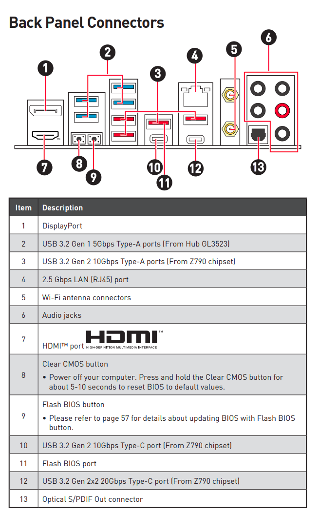
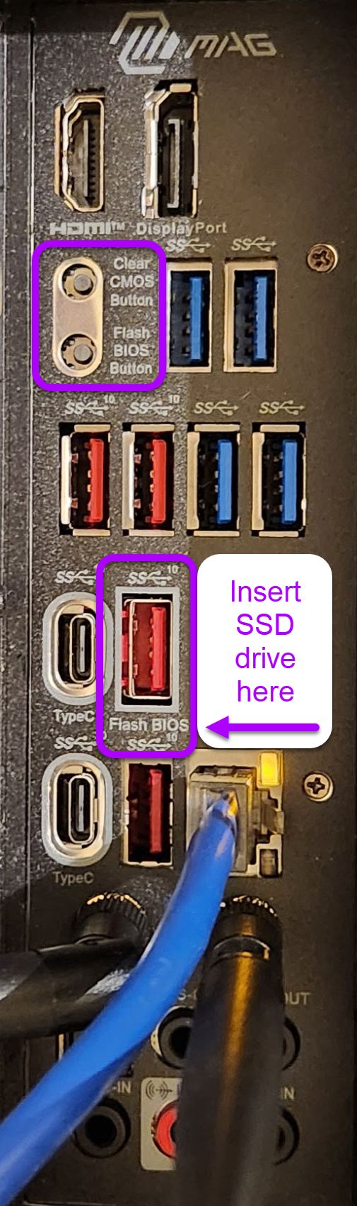
- The Flash BIOS button (shown in the image to the right, and described in the next section) does not require a CPU or a monitor; however, it is somewhat difficult to use because user feedback is limited.
- The BIOS Flash Update requires a CPU and monitor, and gives feedback as you proceed. I much prefer this method. The update is not required in order to run the BIOS. This means you can use an Intel Core i7-13700K to run the BIOS update, even before the BIOS can run an OS.
For both procedures, a USB drive containing the necessary files from the zip file must be plugged into the red USB socket shown in the right-hand image. Both of the procedures described in the following sections require the latest version of the BIOS to be downloaded: AMI BIOS 7D91vHD, created 2024-08-22, a 9.92 MB zip file. The name of the file that I downloaded was 7D91vHD.zip.
The contents of the zip file are handled differently for each of the procedures.
The zip file contains a file called 7D91vHx.txt. It contains information in English, traditional Chinese and simplified Chinese. The English information is:
------------------------------------------------------------------------------------------------
MPG Z790 EDGE WIFI / MAG Z790 TOMAHAWK WIFI (MS-7D91) V17.D BIOS Release
------------------------------------------------------------------------------------------------

1. This is AMI BIOS release

2. This BIOS fixes the following problem of the previous version:
- Update CPU Microcode 0x129

- ME Firmware ver: ME_16.1.30.2361 (download)
ME Firmware update SOP

3. 2024/08/22
Updating BIOS Without a CPU
This method just uses the motherboard, and nothing needs to be connected except a flash drive and the 24-pin power connector. That is, you do not need a CPU, or memory, or a keyboard, or a video card. There is no need for cooling fans for this procedure if no CPU or memory is installed. However, this method can be a bit fiddly to get working.
The procedure is described on page 57 of the User Manual, and in How to Flash the BIOS.
I have added my experience to the following summary of steps to flash the BIOS. The Drivers & Downloads page has all the details.
- Extract the BIOS file from the zip file, which for me was called
E7D91IMS.HD0and was reported as 33,554,432 bytes, even though it was only 10.2 MB packed. So, a 1 GB USB drive would easily accommodate this file. Do not use a USB drive larger than 32 GB. - Rename the BIOS file to
MSI.ROM - Obtain an empty USB drive, 32 GB or smaller, and format it as FAT32. Best if you actually format the drive, instead of just erasing it, to ensure it is properly formatted, with no hidden files on it. If you use the flash drive provided in the box, be sure to format it first to ensure it is empty. Copy
MSI.ROMto the root of the USB drive. - Insert the flash drive into the USB port on the motherboard back panel labeled Flash BIOS.
- Connect the power supply to
CPU_PWR1andATX_PWR1. While there is no need to connectCPU_PWR2, it is fine if you do. - Power on the motherboard.
- Press the CMOS Reset button.
- The manual says this:Press the Flash BIOS button once. About 5 seconds later, the LED next to the USB port will start to flash. After 15 seconds or so, the speed of the flashing light will double, while the BIOS is updated. The LED next to it should flash for 6-7 minutes. The LED will stop flashing when the process completes and the power will turn off.On my system, the LED next to the Flash BIOS button lit up when the button was pushed, but it did not flash. I tried several USB drives, with capacities ranging from 2 GB to 32 GB, with the same result.
Then I tried a 32 GB USB drive, and I pushed Flash, Clear, Flash; the LED started to blink. The LED is not directly visible; it is behind the bezel, between the flash BIOS Button and the red USB port next to it. The light from the LED is easily seen, however. The fans stopped, then restarted, and the LED continued to blink. After several minutes the LED stopped blinking.
The BIOS update was successful.
Updating BIOS With a CPU
Although the available documentation lead me to believe that a supported CPU was required to work with the BIOS, I found that this procedure worked just fine with an Intel Core i7-13700K.
This procedure is described in MSI’s PDF entitled How to update BIOS?.
Unlike the previously discussed procedure, this procedure requires the entire subdirectory structure from the downloaded zip file, and no files or directories should be renamed. Another difference from the other procedure is that the USB drive need not be pristine; other directories and files can be present on the drive. These are the directories and files on the USB drive that were on the SSD drive that I used:
7D91vHD/
  - 7D91vHx.txt
  - E7D91IMS.HD0
Simply boot the system. If no bootable drives are attached the BIOS will appear after a minute or so, and you will be able to use a mouse to click on M-Flash in the lower left area of the screen. A friendly dialog then ensues that provides good feedback. After the system reboots into the BIOS you should see:
 BIOS Ver: E7D91IMS.HD0
 BIOS Build Date: 08/12/2024
USB Headers
Nomenclature for USB 3 has changed over the years, which initially caused me a lot of confusion. Christopher Harper’s article on CG Director entitled What Are USB Headers & How Do You Get More? set me straight. To summarize:
- USB 3.2 Gen 1 is also known as USB 3.0
- USB 3.2 Gen 2 (usually exposed with a USB-C connector) is also known as USB 3.1

MSI MAG Z790 Headers
3 of the 4 USB headers on the MSI MAG Z790 Tomahawk WIFI need cable assemblies with connectors on PCI slot covers. My old Antec case, provides the wiring assembly for 1 USB 2.0 header, which breaks out to 2 USB 2.0 connectors; this assembly routes to the front of the case.
Page 17 of the MSI MAG Z790 Tomahawk User Guide shows the following internal USB headers:
- JUSB1 & JUSB2: 2 USB 2.0 Type-A connectors (From hub GL850G) — supports a total of 4 USB 2.0 ports. I already have one cable assembly for the front of the case as previously mentioned, and I will attach it to JUSB2. 1 additional cable assembly is therefore required for the JUSB1 USB 2.0 header, and it will be routed to a PCI slot cover.
- JUSB3: 1 USB 3.2 Gen 1 5Gbps connector (From hub GL3523) — supports 2 USB 3.2 Gen 1 5Gbps ports. All the cable assemblies that I found were labeled as USB 3.0 compatible, not USB 3.2 Gen 1.
- JUSB4: 1 USB 3.2 Gen 2 10Gbps Type-C front panel connector (From Intel Z790 chipset). Compatible cable assemblies might be labeled as USB 3.1 compatible, or USB 3.2 Gen 2, or USB-C.
.")
, right: JUSB3 (USB 3.2 Gen 1 connector).")

PCI Slot Covers
The case has cutouts for 7 PCI slot covers. The video card uses 2 slots. 5 PCI slot cover cutouts are therefore available.

some extra length would be best.

some extra length would be best.
It is important that as few PCI slot covers are required as possible; thus, each PCI slot cover should have as many connectors on it as possible.

I do not need 4 USB 2.0 connectors on a PCI slot cover. Below is a mock-up of the desired cable assembly.
It would be best if both USB 2.0 connectors were attached to the same PCI slot cover as the USB 3.2 Gen 1 connectors, as shown below.

However, if the USB 3.2 Gen 1 connectors are only available together on a separate PCI slot cover, that would also work. As previously mentioned, the USB 3.2 Gen 1 cable in the above assembly should be at least 33 cm long.

The USB-C connector might look like this (again, the cable should be least 33 cm long):

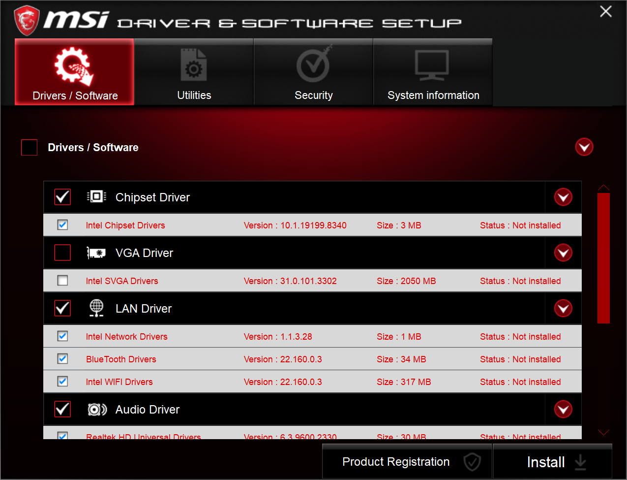
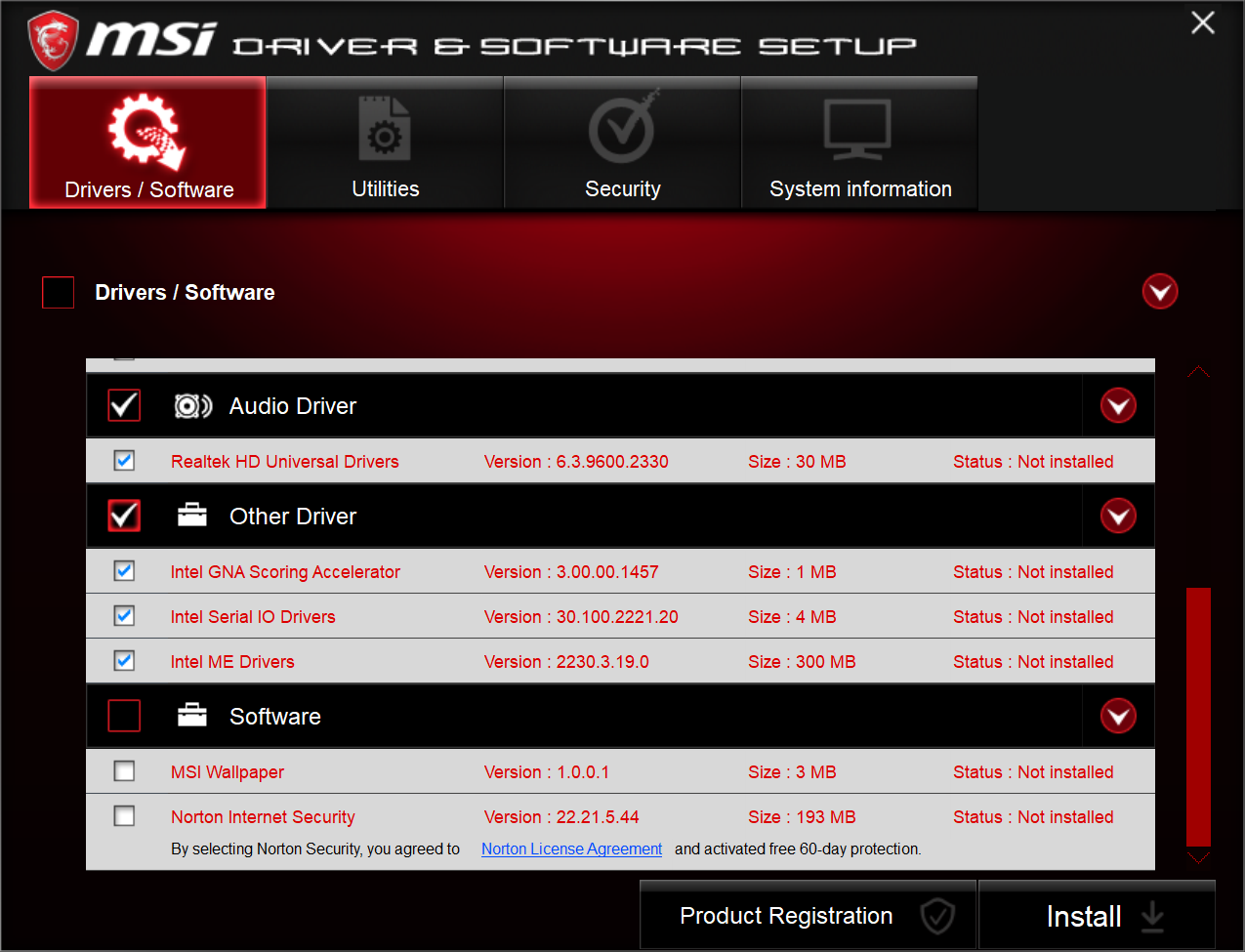
MSI Software
The new system came right up and I logged into Windows without any issues. I was amazed! The drivers had to be installed before the network could be accessed, so I inserted the USB drive that came with the motherboard, and double-clicked the ISO image to mount it. The MSI software and drivers installed without issue, and everything worked, even WSL 2 with systemd and graphics support. Unbelievable!